
B-series transmission teardown/rebuild tutorial
 12-02-2008, 06:24 PM
#1
Honda-Tech Member
Thread Starter
Join Date: Nov 2004
Location: 40.201N, 77.189W, PA
Posts: 4,738
Likes: 0
Received 7 Likes
on
4 Posts
!!! K-SERIES OWNERS, FURTHER DOWN THIS PAGE IS APPLICABLE STEPS TO MOST K-SERIES TEARDOWNS !!!
Okay, well, I’ve been seeing that several of the good transmission teardown and rebuild threads created by valuable H-T members (IN VTEC, Bauley Civic, Bense, etc.) have been either removed or lack photos at current, so I decided to provide whatever aid I can in this manner to this site which has always helped me. So hopefully some DIY’er can find some help from this, or even someone can perhaps gain an interest in possibly attempting it. I promise, you needn’t be afraid of transmissions – manual ones, at least.
But bear with me, as I may go over and edit various parts of this to fine tune it. It’s taking some time, but it’ll get there. I just want it as easy to use, read, and understand as possible. And I’m open to suggestions if you find something odd or think something may need explained more, or even period.
BACKGROUND:
The transmission I will go over is my spare 1995 GSR transmission I’ve had lying around for two years now. Luckily, I knew what was wrong with it prior to opening it up this time, as I had it in my car for about two months at one point. It was excellent everywhere, except it ground 3rd at anything above 5500 rpm. So this is what I will set out to fix for this tutorial. I assumed that it’ll be the synchronizer, and have a used one available that I received for doing some transmission work for a friend of mine. So we’ll open it up, inspect various parts, replace the synchronizer, and seal the transmission back up.
TOOL LIST:
The bare minimum you need to simply open the casing up and reseal it:
2x4 blocks of wood (2)
1/2” ratchet (1)
3/8” ratchet (1)
10mm 3/8” deep-well socket (1)
12mm 3/8” socket (1)
14mm 3/8” socket (1)
Needle nose pliers (1)
Razor blade (1)
Tube of Honda Bond (1)
8” - 17”pry bar (2)
Helpful:
3/8” extensions
1/2” extensions
Dead-blow mallet (1)
Torque wrench (1)
Magnet (1)
Required to replace synchronizers (mainshaft):
3-arm bearing puller
Required to replace synchronizers (countershaft):
3-arm bearing puller
32mm 1/2” socket
1/2” air gun with compressor (or a big breaker bar and some luck) (1)
Bench mounted vice (1)
GENERAL RULE: I have tried to keep all explanations appearing ABOVE the photos posted. If you see a photo and want to see specifically what is being written regarding that photo, scroll up to the first paragraph above.
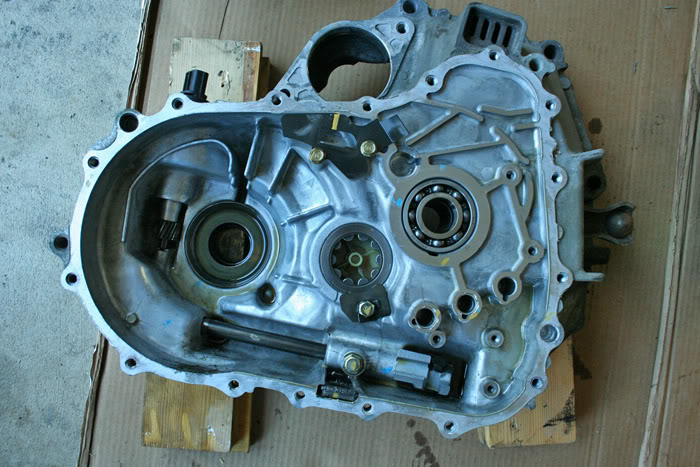
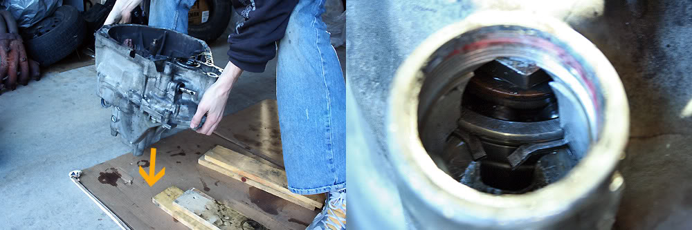
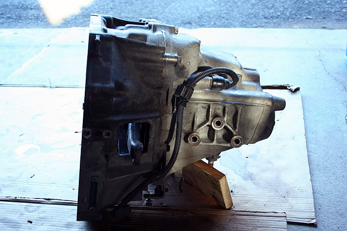
Here you can see the transmission mounted up on two simple blocks of wood. This allows the transmission to be elevated so that the mainshaft does not bottom out against the ground. This is vital for trying to seal up the case at the end of the process.
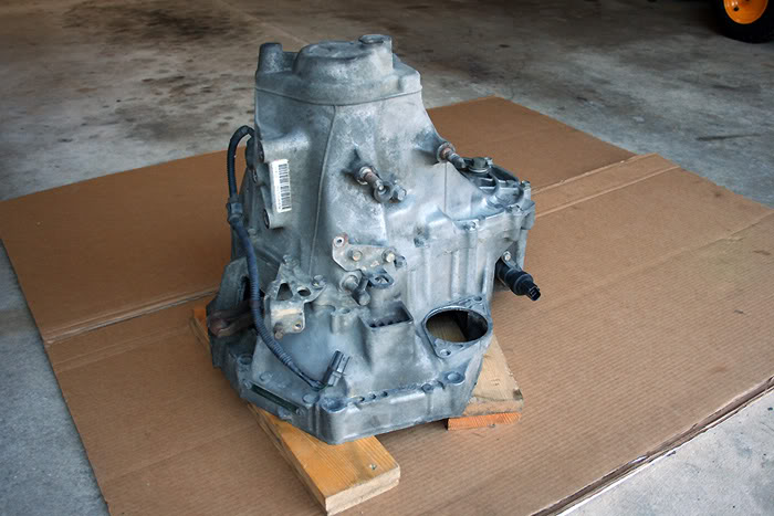
Just another angle of the transmission.
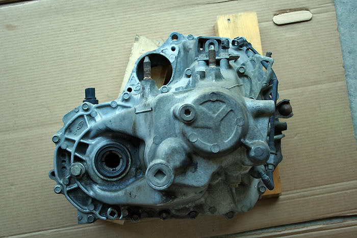
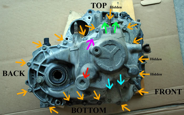
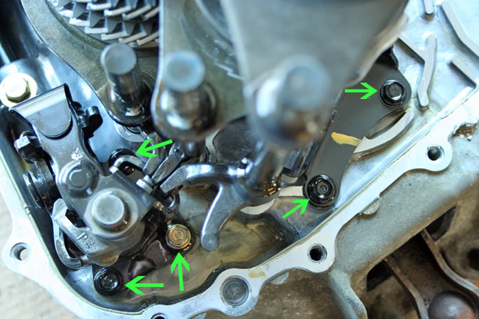
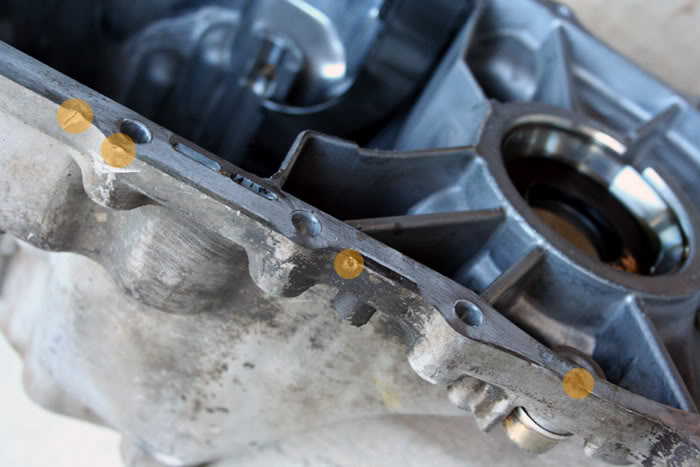
Same view with some descriptions.
RED – C-clip bolt with 1/2” socket bolt (1)
PURPLE – 14mm reverse idler gear bolt (1)
GREEN – 12mm bracket bolts (2)
TEAL – 12mm shifter bolts (2)
ORANGE – 12mm transmission case bolts (17) – 3 bolts are hidden from view due to the camera angle
Also pictured are the speed sensor, reverse sensor, oil drain plug, and oil fill plug. None of these need removed to proceed.
So, we can now begin digging into this thing. Remove both 12mm bolts (TEAL ARROWS in the previous photo) and washers which retain the shift fork springs and *****; take care not to lose the ***** – a magnet will help extract them out of the bolt holes securely. You can also simply cusp your hand beneath each bolt hole and tip the transmission over so that the ***** roll out.
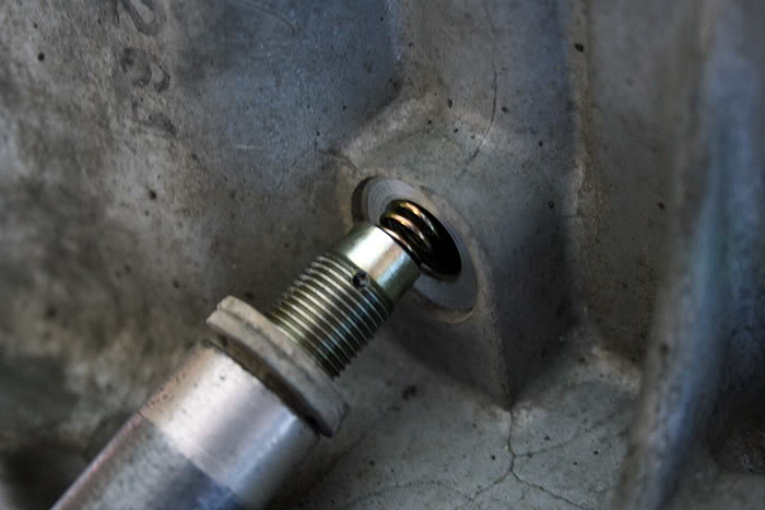
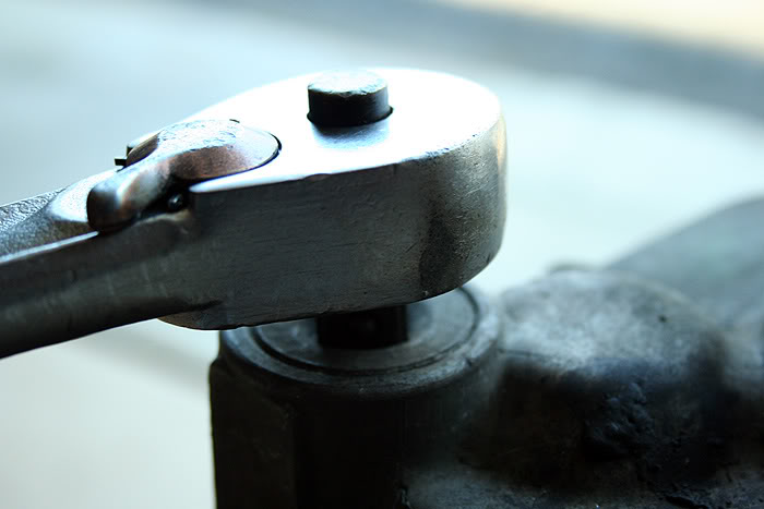
Remove the 14mm reverse idler shaft bolt (PURPLE ARROW) with its washer. Then, simply by using the �” ratchet, remove the c-clip retaining bolt (RED ARROW).
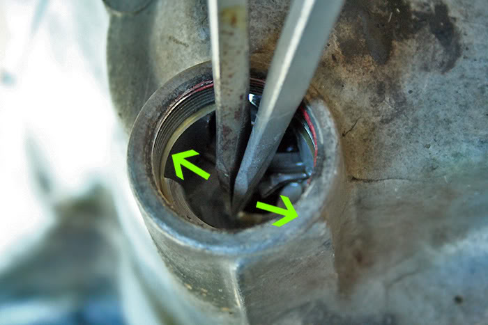
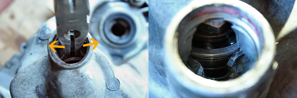
Now you can remove the c-clip from the groove in the countershaft bearing. There are several ways this can be achieved: 1) snap ring pliers; 2) needle nose pliers; 3) two flathead screwdrivers. The snap ring pliers are the easiest method, as you just have to squeeze the handle together. I normally just use the needle nose pliers, but you will typically have to use both hands to spread the handle apart. You will also need to use both hands to use the two screwdrivers. Regardless of the method, get the tips of the tools in between the two ends of the c-clip and pry it apart. The countershaft will drop due to its weight, and you will be notified of this drop by a distinct “clunk”.
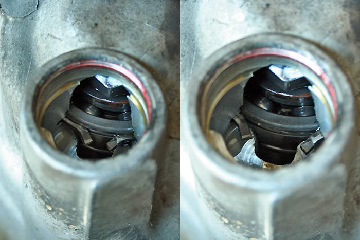
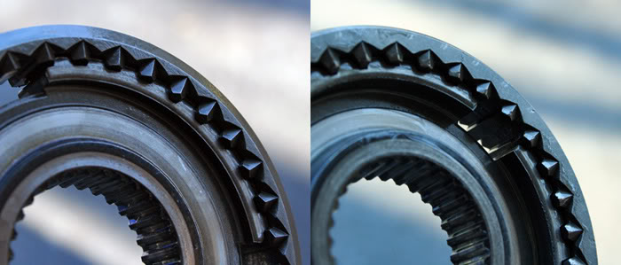
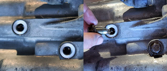
Here is a BEFORE and AFTER of the c-clip.
Remove the two 12mm bolts (GREEN ARROWS) to the bracket at the top side of the transmission by the vent. These will uncover another 12mm bolt responsible for holding the two cases together.
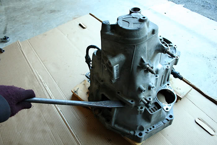
Finish by then removing the remaining 17 12mm bolts (ORANGE ARROWS) which keep the two cases together. Once they are out, you are ready to pry the upper casing from the bell housing. Get a prying mechanism (pry bar, tire iron, etc.) and place one end into the available slot on the front side of the transmission – this unfortunately is the only decent prying point on the B-series and K-series transmission; D-series on the other hand have two pry points.
Once you pry that up, you’ll notice that the other end of the transmission had a difficult time coming apart. There are two locating pins between the two housings which could get damaged by further prying like that. So get another pry bar or even a flathead screwdriver, and go to town on the other end of the transmission. It will normally pop right open with ease.
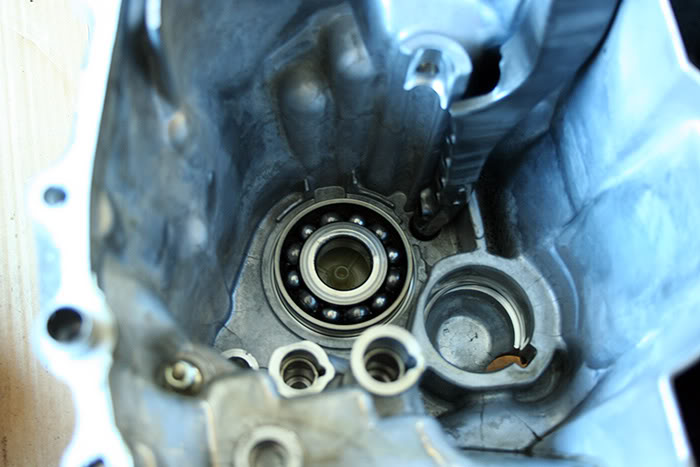
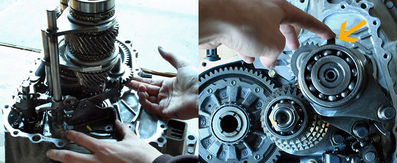
With the two cases now fully separated, simply lift the casing straight up, taking care to avoid heavy contact with the gear clusters inside. If you are having difficulty with this, it could be a few things. The bearing on the top of the mainshaft (commonly referred to as the input shaft bearing, or ISB) is tight in the casing and on the mainshaft, causing some trouble. The peskier issue is when a sealed differential bearing becomes tight in the passenger side transmission case. When this happens, as you pull the case up, the differential pulls with it, ultimately hitting the countershaft and preventing you from pulling the casing up any further. Either way, light taps to the casing with a dead blow hammer will normally free up these bearings. The roller bearings of the older GSR and ITR transmissions (those found in this particular GSR transmission) will never have this problem in the teardown and rebuild process.
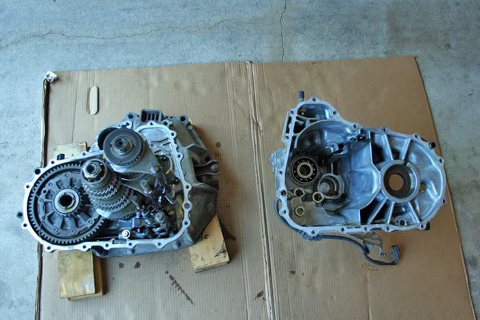
These are the two casing halves separated finally. In the second photo, you can see that the mainshaft bearing has pulled up with the casing. If this happens, tap the casing against the surface you are working on to make the bearing drop out (it is nice to have a towel or something down to catch the bearing with to give it a soft landing).
Proceed to remove the 5 10mm bolts (four black and one gold) holding in the shift change assembly and reverse change holder to the bell housing. A thin-walled deep-well socket will make getting to the bolts of the shift change assembly easy. It is difficult with non-deep-well sockets, and almost impossible with wrenches. Then, just lift the two pieces, along with the reverse gear and idler shaft, out of the casing. The shift forks may need to be placed in their neutral settings to make the removal of the shift change assembly in one piece pretty simple.


Now, grab the two gear sets and three shift forks with both hands and lift straight up, taking care not to accidentally lose anything from the mainshaft assembly when you lay the gear sets down, as the mainshaft pieces are not held on with a locknut like those of the countershaft. There is also a thrust washer and a shim to be aware of resting at the base of the mainshaft assembly. They will sometimes come out with the mainshaft, and sometimes they will be left behind resting on the casing’s mainshaft bearing. It is incredibly important to keep these two pieces in their appropriate locations (the thrust washer’s outward curved surface will rest against the bell housing’s mainshaft bearing). You can pull these out and place them on the mainshaft again, or just leave them on the bearing.
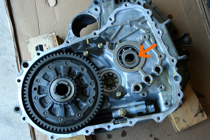
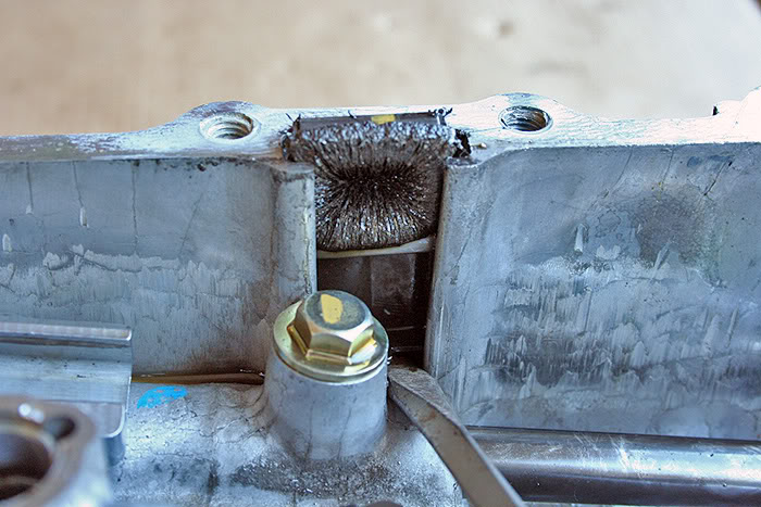
This is the casing torn down to just the bare minimum. Gear sets, differential, reverse idler, shift forks, and change holders have all been removed. Under where the differential was resting, you can also see where the speed sensor locates itself inside the transmission casing. You can now inspect the two bearings in the bell housing for any damage, unusual scarring, or excessive play. Also, the three tabs which hold the shift forks will have quite a bit of play, but they should not have excessive play, when you place the shift forks in them.
To be cont'd...
Okay, well, I’ve been seeing that several of the good transmission teardown and rebuild threads created by valuable H-T members (IN VTEC, Bauley Civic, Bense, etc.) have been either removed or lack photos at current, so I decided to provide whatever aid I can in this manner to this site which has always helped me. So hopefully some DIY’er can find some help from this, or even someone can perhaps gain an interest in possibly attempting it. I promise, you needn’t be afraid of transmissions – manual ones, at least.
But bear with me, as I may go over and edit various parts of this to fine tune it. It’s taking some time, but it’ll get there. I just want it as easy to use, read, and understand as possible. And I’m open to suggestions if you find something odd or think something may need explained more, or even period.
BACKGROUND:
The transmission I will go over is my spare 1995 GSR transmission I’ve had lying around for two years now. Luckily, I knew what was wrong with it prior to opening it up this time, as I had it in my car for about two months at one point. It was excellent everywhere, except it ground 3rd at anything above 5500 rpm. So this is what I will set out to fix for this tutorial. I assumed that it’ll be the synchronizer, and have a used one available that I received for doing some transmission work for a friend of mine. So we’ll open it up, inspect various parts, replace the synchronizer, and seal the transmission back up.
TOOL LIST:
The bare minimum you need to simply open the casing up and reseal it:
2x4 blocks of wood (2)
1/2” ratchet (1)
3/8” ratchet (1)
10mm 3/8” deep-well socket (1)
12mm 3/8” socket (1)
14mm 3/8” socket (1)
Needle nose pliers (1)
Razor blade (1)
Tube of Honda Bond (1)
8” - 17”pry bar (2)
Helpful:
3/8” extensions
1/2” extensions
Dead-blow mallet (1)
Torque wrench (1)
Magnet (1)
Required to replace synchronizers (mainshaft):
3-arm bearing puller
Required to replace synchronizers (countershaft):
3-arm bearing puller
32mm 1/2” socket
1/2” air gun with compressor (or a big breaker bar and some luck) (1)
Bench mounted vice (1)
GENERAL RULE: I have tried to keep all explanations appearing ABOVE the photos posted. If you see a photo and want to see specifically what is being written regarding that photo, scroll up to the first paragraph above.
Here you can see the transmission mounted up on two simple blocks of wood. This allows the transmission to be elevated so that the mainshaft does not bottom out against the ground. This is vital for trying to seal up the case at the end of the process.
Just another angle of the transmission.
Same view with some descriptions.
RED – C-clip bolt with 1/2” socket bolt (1)
PURPLE – 14mm reverse idler gear bolt (1)
GREEN – 12mm bracket bolts (2)
TEAL – 12mm shifter bolts (2)
ORANGE – 12mm transmission case bolts (17) – 3 bolts are hidden from view due to the camera angle
Also pictured are the speed sensor, reverse sensor, oil drain plug, and oil fill plug. None of these need removed to proceed.
So, we can now begin digging into this thing. Remove both 12mm bolts (TEAL ARROWS in the previous photo) and washers which retain the shift fork springs and *****; take care not to lose the ***** – a magnet will help extract them out of the bolt holes securely. You can also simply cusp your hand beneath each bolt hole and tip the transmission over so that the ***** roll out.
Remove the 14mm reverse idler shaft bolt (PURPLE ARROW) with its washer. Then, simply by using the �” ratchet, remove the c-clip retaining bolt (RED ARROW).
Now you can remove the c-clip from the groove in the countershaft bearing. There are several ways this can be achieved: 1) snap ring pliers; 2) needle nose pliers; 3) two flathead screwdrivers. The snap ring pliers are the easiest method, as you just have to squeeze the handle together. I normally just use the needle nose pliers, but you will typically have to use both hands to spread the handle apart. You will also need to use both hands to use the two screwdrivers. Regardless of the method, get the tips of the tools in between the two ends of the c-clip and pry it apart. The countershaft will drop due to its weight, and you will be notified of this drop by a distinct “clunk”.
Here is a BEFORE and AFTER of the c-clip.
Remove the two 12mm bolts (GREEN ARROWS) to the bracket at the top side of the transmission by the vent. These will uncover another 12mm bolt responsible for holding the two cases together.
Finish by then removing the remaining 17 12mm bolts (ORANGE ARROWS) which keep the two cases together. Once they are out, you are ready to pry the upper casing from the bell housing. Get a prying mechanism (pry bar, tire iron, etc.) and place one end into the available slot on the front side of the transmission – this unfortunately is the only decent prying point on the B-series and K-series transmission; D-series on the other hand have two pry points.
Once you pry that up, you’ll notice that the other end of the transmission had a difficult time coming apart. There are two locating pins between the two housings which could get damaged by further prying like that. So get another pry bar or even a flathead screwdriver, and go to town on the other end of the transmission. It will normally pop right open with ease.
With the two cases now fully separated, simply lift the casing straight up, taking care to avoid heavy contact with the gear clusters inside. If you are having difficulty with this, it could be a few things. The bearing on the top of the mainshaft (commonly referred to as the input shaft bearing, or ISB) is tight in the casing and on the mainshaft, causing some trouble. The peskier issue is when a sealed differential bearing becomes tight in the passenger side transmission case. When this happens, as you pull the case up, the differential pulls with it, ultimately hitting the countershaft and preventing you from pulling the casing up any further. Either way, light taps to the casing with a dead blow hammer will normally free up these bearings. The roller bearings of the older GSR and ITR transmissions (those found in this particular GSR transmission) will never have this problem in the teardown and rebuild process.
These are the two casing halves separated finally. In the second photo, you can see that the mainshaft bearing has pulled up with the casing. If this happens, tap the casing against the surface you are working on to make the bearing drop out (it is nice to have a towel or something down to catch the bearing with to give it a soft landing).
Proceed to remove the 5 10mm bolts (four black and one gold) holding in the shift change assembly and reverse change holder to the bell housing. A thin-walled deep-well socket will make getting to the bolts of the shift change assembly easy. It is difficult with non-deep-well sockets, and almost impossible with wrenches. Then, just lift the two pieces, along with the reverse gear and idler shaft, out of the casing. The shift forks may need to be placed in their neutral settings to make the removal of the shift change assembly in one piece pretty simple.
Now, grab the two gear sets and three shift forks with both hands and lift straight up, taking care not to accidentally lose anything from the mainshaft assembly when you lay the gear sets down, as the mainshaft pieces are not held on with a locknut like those of the countershaft. There is also a thrust washer and a shim to be aware of resting at the base of the mainshaft assembly. They will sometimes come out with the mainshaft, and sometimes they will be left behind resting on the casing’s mainshaft bearing. It is incredibly important to keep these two pieces in their appropriate locations (the thrust washer’s outward curved surface will rest against the bell housing’s mainshaft bearing). You can pull these out and place them on the mainshaft again, or just leave them on the bearing.
This is the casing torn down to just the bare minimum. Gear sets, differential, reverse idler, shift forks, and change holders have all been removed. Under where the differential was resting, you can also see where the speed sensor locates itself inside the transmission casing. You can now inspect the two bearings in the bell housing for any damage, unusual scarring, or excessive play. Also, the three tabs which hold the shift forks will have quite a bit of play, but they should not have excessive play, when you place the shift forks in them.
To be cont'd...
Last edited by Honda Bull; 12-06-2008 at 10:50 AM.

The following 3 users liked this post by Honda Bull:
12-02-2008, 06:33 PM
#2
Honda-Tech Member
Thread Starter
Join Date: Nov 2004
Location: 40.201N, 77.189W, PA
Posts: 4,738
Likes: 0
Received 7 Likes
on
4 Posts
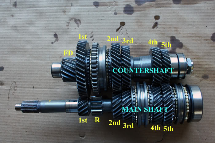
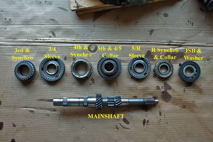
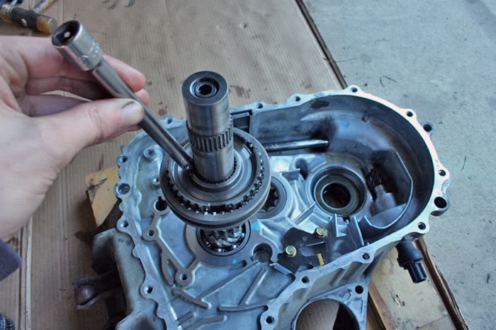
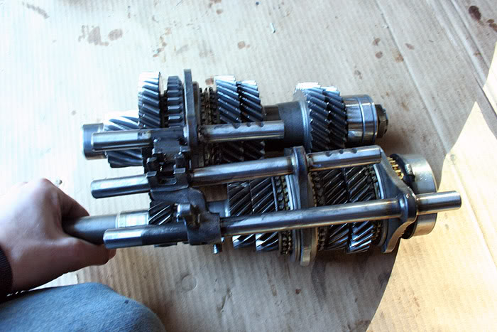
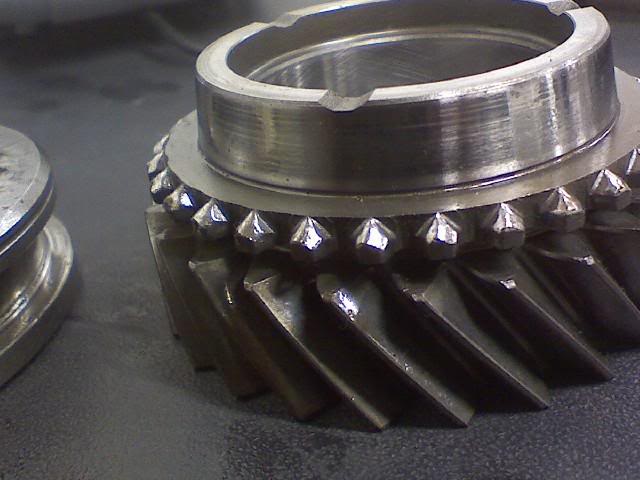
Now, since I am replacing a 3rd gear synchronizer in this transmission, I must pull the mainshaft apart to reach the synchronized 3rd gear in the transmission. By looking at the next photo, you can see why the mainshaft is the gear cluster we are tearing apart to do this. Honda has placed the synchronizer hub for 3rd and 4th gears on the mainshaft – this is the piece between 3rd and 4th gears on the mainshaft. The gold colored piece on the 3rd gear side of this hub is the synchronizer ring that most likely needs replaced.
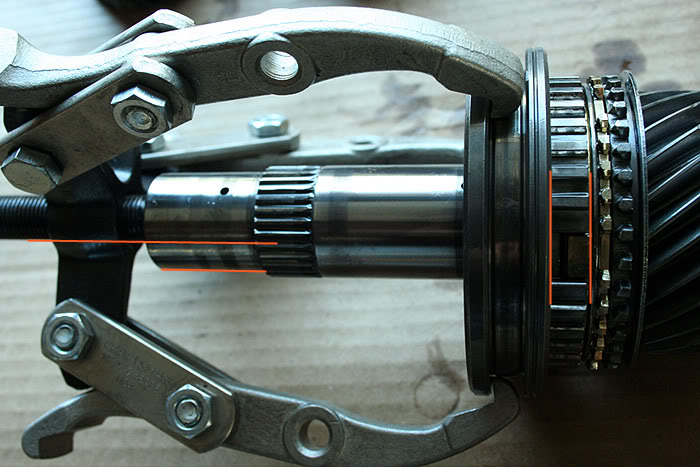
Now, I have already begun pulling pieces off of the mainshaft. Don’t get too scared or frustrated with this process. Always take your time and stay organized. By following those two basic instructions, you won’t lose track of anything. I have removed the pieces and placed them with their tops facing down on the cardboard. When you finally reach the synchronizer hub, you may or may not need a bearing puller. The first two transmissions I ever messed with I did not need one – the synchronizer sleeve and hub slid right off. Every transmission since, however, has required a bearing pulled to remove this piece from the mainshaft. Just make sure the bearing puller’s threading bolt is lined up parallel to the mainshaft, and that the bearing puller’s arms (I prefer to use a 3-arm bearing puller) are pulling up on the sleeve in such a way that the sleeve remains parallel to the hub. Then twist until it frees up, making sure there is no binding or unusual pressure stiffness as the hub is being removed.
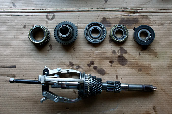
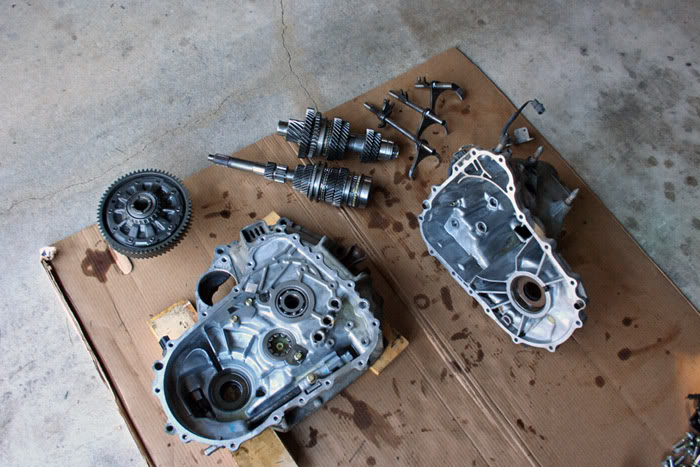
Voila! The mainshaft has been completely disassembled and its parts have been neatly ordered.
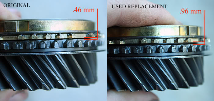
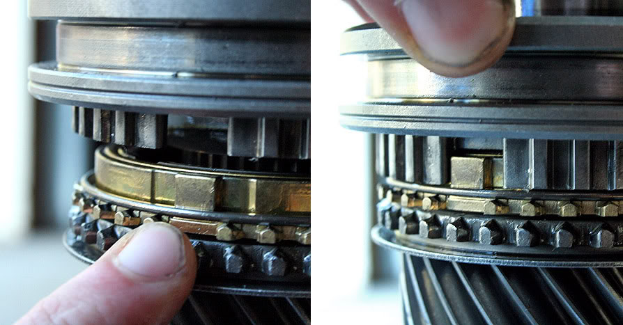
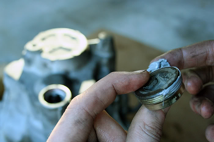
We can begin to measure the specified clearance of the synchronizer(s). Pick up 3rd gear and its brass synchronizer ring. Firmly, and evenly, press the ring against the gear. Then simply take a feeler gauge and figure out the gap between the bottom of the synchronizer ring and the gear. I’m actually replacing this worn down synchronizer ring with another used synchronizer ring which I knew was still in good condition. So I, too, measured the clearance of the replacement synchronizer I had available to double-check. You can visibly see the difference in the gap between the two synchronizers. And the measurement confirms that. The old synchronizer was marginally above service limit, and the replacement synchronizer was in the middle of its acceptable clearance range.
NOTE: This measuring process does not always guarantee a working or worn synchronizer, but usually does offer a good starting point. Even if a synchro is still in the proper range, it, or other parts, can still have wear issues which prevent its proper functioning.
Now, it is time to address the gear cone and the synchronizer sleeve and hub. The gear cone will develop heat spots and wear marks just like a brake disc or a flywheel. In this particular instance, there were several unusual wear marks on the gear cone surface. To ensure the best possible braking surface for the new synchronizer, it helps to scuff the gear cone. Many people use sand paper (400-800 grit) and travel in a circular or crisscross pattern. This is the same idea as resurfacing a flywheel for the installation of a new clutch.
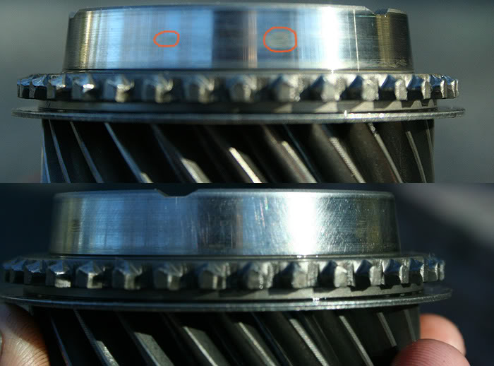
Inspect the synchronizer hub(s) for any wear. Mine unfortunately had pretty bad wear, but I didn’t have another hub in better condition to use in its place right now. I plan to test this tranny out again: if it still grinds 3rd, I’ll know that this wear on the hub more than likely was the issue.
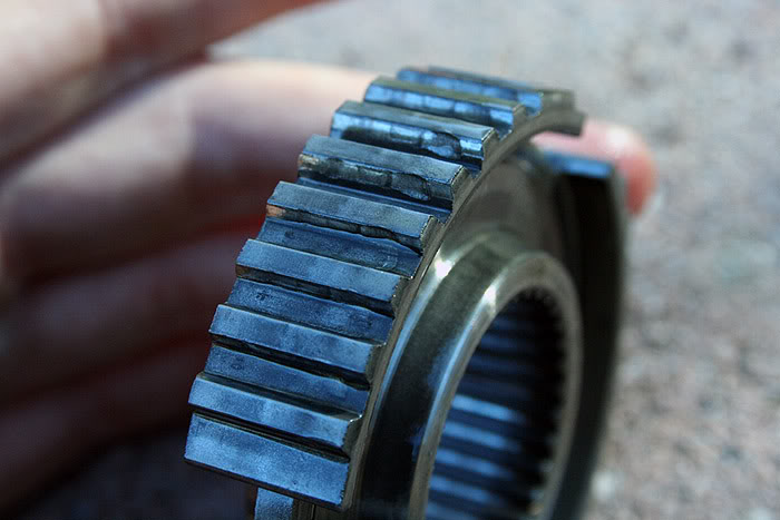
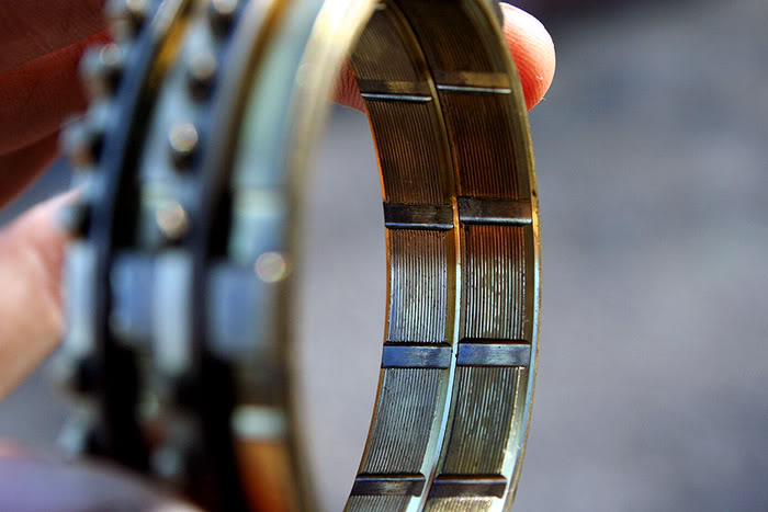
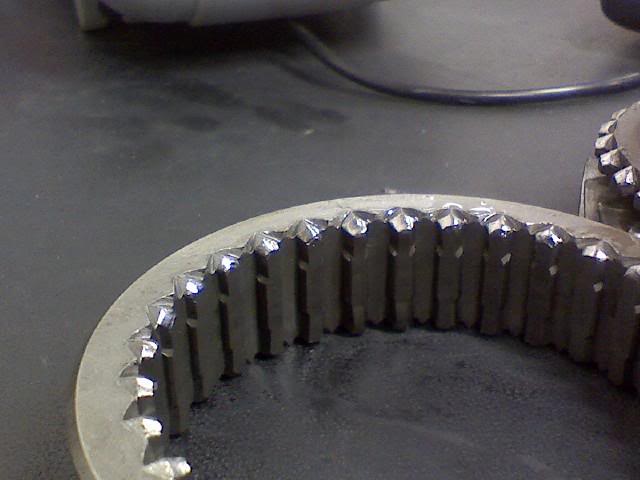
Also, inspect the teeth on the inside of the synchronizer sleeve(s). In this photo, I have the 5th/Reverse synchronizer sleeve to clearly illustrate wear. On the left are the Reverse side teeth. They are full and clearly retain their original edge. On the right is the 5th gear side of the sleeve. It is clearly showing some 75,000+ mile wear and abuse with an operational synchronizer. These can get very, very ugly when a synchronizer has gone bad and the owner continues to use that gear.
Now that inspection of the internal parts is complete, reassembly can now be undertaken. Place the pieces on the shaft in the same manner and order you removed them – 3rd gear needle bearing, 3rd gear, 3rd gear synchronizer and blocking ring, 3rd/4th synchronizer hub and sleeve, 4th gear needle bearing and collar, 4th gear, and so on…
NOTE: While installing all of the parts on the mainshaft, lubricate all bearing surfaces and bearings with oil. Also, lubricate the gear cones with oil as well. Oil is not necessary on any gear or hub’s splines that press on over the splines of the main or countershaft.
When you reach the 3rd/4th gear hub, however, you will need to press it on. A press is highly recommended, but you can do this safely a number of different ways. The best alternative to a press is to, using a dead-blow hammer, tap the hub onto the splines of the mainshaft with another pipe or tube that both fits over the mainshaft but on the surface of the hub. I have also made use of a socket extension, lightly tapping on it at alternating points around the hub. The most important thing to do is to make sure that the hub matches up level and evenly to the splines of the mainshaft by pressing the hub down by hand. Then follow this action up with tapping.
While performing this, be aware of the alignment of the synchronizer tabs and the slots for the tabs in the hub.
If there is remaining work to perform on the differential or the countershaft, do it now. Search on here for another thread pertaining to this, or perhaps I may do another tutorial involving these. We now have all of the parts ready to go back together.
To be cont'd...
Now, I have already begun pulling pieces off of the mainshaft. Don’t get too scared or frustrated with this process. Always take your time and stay organized. By following those two basic instructions, you won’t lose track of anything. I have removed the pieces and placed them with their tops facing down on the cardboard. When you finally reach the synchronizer hub, you may or may not need a bearing puller. The first two transmissions I ever messed with I did not need one – the synchronizer sleeve and hub slid right off. Every transmission since, however, has required a bearing pulled to remove this piece from the mainshaft. Just make sure the bearing puller’s threading bolt is lined up parallel to the mainshaft, and that the bearing puller’s arms (I prefer to use a 3-arm bearing puller) are pulling up on the sleeve in such a way that the sleeve remains parallel to the hub. Then twist until it frees up, making sure there is no binding or unusual pressure stiffness as the hub is being removed.
Voila! The mainshaft has been completely disassembled and its parts have been neatly ordered.
We can begin to measure the specified clearance of the synchronizer(s). Pick up 3rd gear and its brass synchronizer ring. Firmly, and evenly, press the ring against the gear. Then simply take a feeler gauge and figure out the gap between the bottom of the synchronizer ring and the gear. I’m actually replacing this worn down synchronizer ring with another used synchronizer ring which I knew was still in good condition. So I, too, measured the clearance of the replacement synchronizer I had available to double-check. You can visibly see the difference in the gap between the two synchronizers. And the measurement confirms that. The old synchronizer was marginally above service limit, and the replacement synchronizer was in the middle of its acceptable clearance range.
NOTE: This measuring process does not always guarantee a working or worn synchronizer, but usually does offer a good starting point. Even if a synchro is still in the proper range, it, or other parts, can still have wear issues which prevent its proper functioning.
Now, it is time to address the gear cone and the synchronizer sleeve and hub. The gear cone will develop heat spots and wear marks just like a brake disc or a flywheel. In this particular instance, there were several unusual wear marks on the gear cone surface. To ensure the best possible braking surface for the new synchronizer, it helps to scuff the gear cone. Many people use sand paper (400-800 grit) and travel in a circular or crisscross pattern. This is the same idea as resurfacing a flywheel for the installation of a new clutch.
Inspect the synchronizer hub(s) for any wear. Mine unfortunately had pretty bad wear, but I didn’t have another hub in better condition to use in its place right now. I plan to test this tranny out again: if it still grinds 3rd, I’ll know that this wear on the hub more than likely was the issue.
Also, inspect the teeth on the inside of the synchronizer sleeve(s). In this photo, I have the 5th/Reverse synchronizer sleeve to clearly illustrate wear. On the left are the Reverse side teeth. They are full and clearly retain their original edge. On the right is the 5th gear side of the sleeve. It is clearly showing some 75,000+ mile wear and abuse with an operational synchronizer. These can get very, very ugly when a synchronizer has gone bad and the owner continues to use that gear.
Now that inspection of the internal parts is complete, reassembly can now be undertaken. Place the pieces on the shaft in the same manner and order you removed them – 3rd gear needle bearing, 3rd gear, 3rd gear synchronizer and blocking ring, 3rd/4th synchronizer hub and sleeve, 4th gear needle bearing and collar, 4th gear, and so on…
NOTE: While installing all of the parts on the mainshaft, lubricate all bearing surfaces and bearings with oil. Also, lubricate the gear cones with oil as well. Oil is not necessary on any gear or hub’s splines that press on over the splines of the main or countershaft.
When you reach the 3rd/4th gear hub, however, you will need to press it on. A press is highly recommended, but you can do this safely a number of different ways. The best alternative to a press is to, using a dead-blow hammer, tap the hub onto the splines of the mainshaft with another pipe or tube that both fits over the mainshaft but on the surface of the hub. I have also made use of a socket extension, lightly tapping on it at alternating points around the hub. The most important thing to do is to make sure that the hub matches up level and evenly to the splines of the mainshaft by pressing the hub down by hand. Then follow this action up with tapping.
While performing this, be aware of the alignment of the synchronizer tabs and the slots for the tabs in the hub.
If there is remaining work to perform on the differential or the countershaft, do it now. Search on here for another thread pertaining to this, or perhaps I may do another tutorial involving these. We now have all of the parts ready to go back together.
To be cont'd...
Last edited by Honda Bull; 12-02-2008 at 06:42 PM.
The following users liked this post:
12-02-2008, 06:40 PM
#3
Honda-Tech Member
Thread Starter
Join Date: Nov 2004
Location: 40.201N, 77.189W, PA
Posts: 4,738
Likes: 0
Received 7 Likes
on
4 Posts
Go ahead and clean the transmission casings. Get as much of the old oil out as possible. You can do this with various substances. Carburetor cleaner works well. I try to avoid brake cleaner so that I don’t get any on the bearings. I had very little oil left in this transmission when I opened it up, so I didn’t even bother this time. Beyond that, you can pry out the magnet with a flathead screwdriver and wipe it off – if anyone has a great way to clean a magnet, please tell! Also, scrape off the old gasket sealer on the mating surfaces of both transmission case halves. Razor blades or gasket scrapers work well. Just be careful not to gouge the mating surface much with the blades. Then wipe it off with the carb cleaner and paper towel to keep it clean and dry.
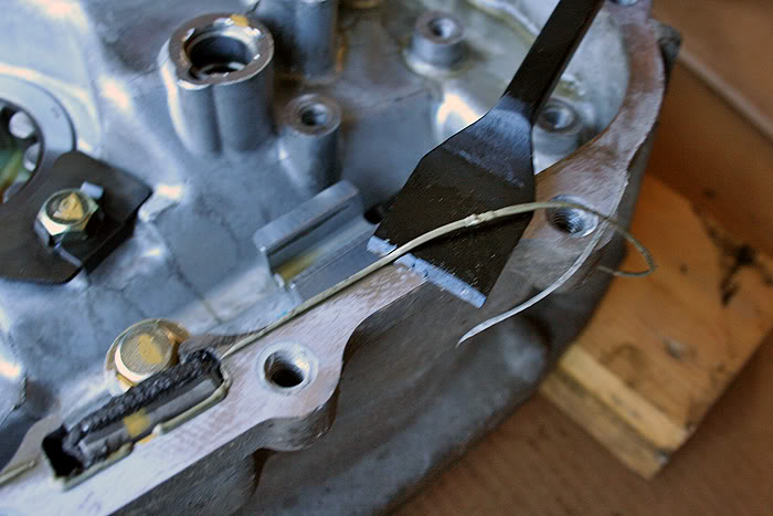
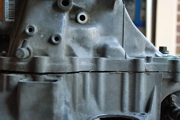
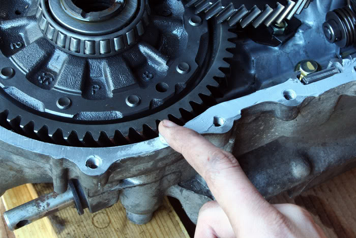
Another thing to look out for which may hinder the sealing of the case halves are scores that may need filed down. Mine did have some damage, highlighted in orange, which I filed down and wiped down.
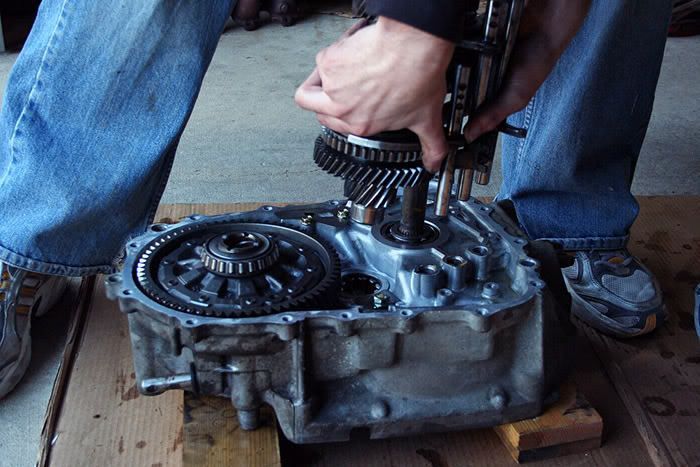
With that done, we can get back to reassembly. Put the differential back in. Next, align the gear clusters with the shift forks like so, and reinstall them in the bell housing.
NOTE: This is a billion times easier with two people, as it can be quite difficult to both hold the gear clusters and turn the differential if the countershaft’s final drive pinion gear is having trouble lining up with the final drive ring gear of the differential.
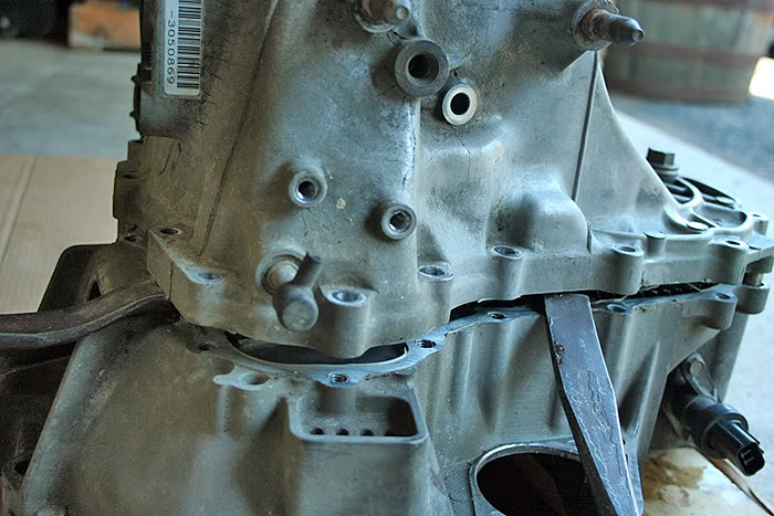
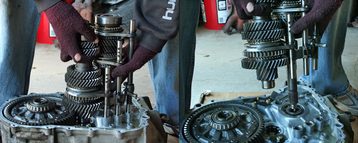
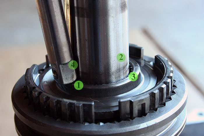
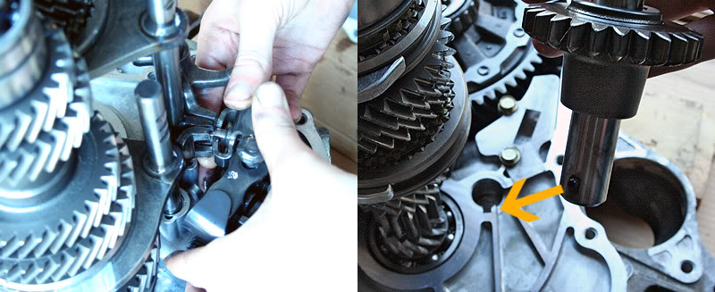
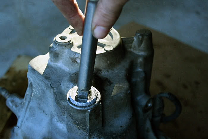
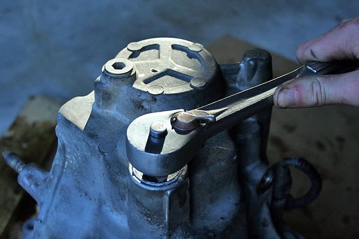
Once complete, install the shift change assembly and the reverse idler gear. Make sure that the shift rod in the casing is in neutral, as well as all three shift forks. In neutral, the shift assembly will drop down into its place in the casing. Just maintain upward pressure of the shift forks with right index finger and downward pressure on the shift change assembly’s alignment rod with your left thumb, as seen in the right photo. Once in, reinstall the three 10mm bolts. Only tighten them gently by hand, as they can be easy to strip out. In the left photo, you can see the pin on the reverse idler that needs lined up with the slot in the transmission casing.
Next, place the reverse change holder in its place, aligned with the 5/R shift fork and the reverse idler gear. Thread its two 10mm bolts in gently by hand. Finally, make sure to move the alignment tab of the mainshaft washer to roughly the 12 o’clock position – you can see where this tab locates in the upper casing.
NOTE: Before spreading the gasket sealer on the mating surface of the bell housing, it may be helpful to run through closing the transmission case once or twice if it is your first time. This may help eliminate any surprises and resulting frustrations. As much as I have done this, I still hit snags every so often. I had a differential bearing with a slight burr prevent the casing from falling down completely. I spent about thirty minutes looking for the problem before finding it, and by that time the gasket sealer was spent.
Comfortable with the next few steps, go ahead and spread the gasket sealer. I strongly recommend Honda Bond, as that stuff is probably used to seal cracks in the Hoover Dam, but I’ve used almost all variations of RTV Sealant (gray, blue, red, black) with great results. Yes, I was being cheap.
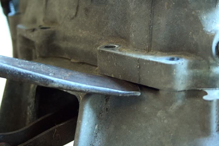
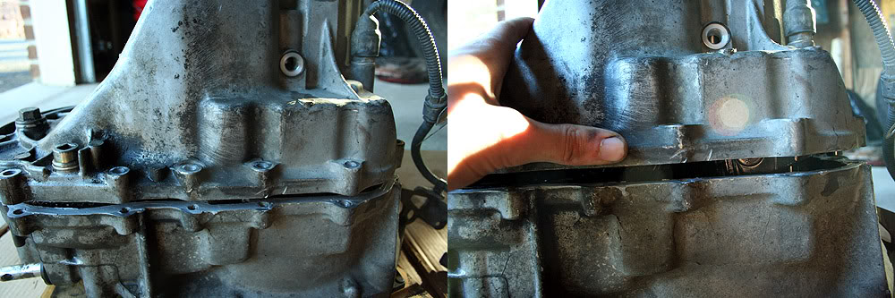
Once you have gasket sealer spread all around the mating surface of the bell housing, go ahead and slide the upper casing down over the gear cluster, making sure you don’t bump the tab you aligned at 12 o’clock. The picture on the right shows the “thumbnail” gap that you’ll normally see when the case bottoms out on the shift change assembly’s alignment rod.
The easiest way I’ve found to drop the case further down is to use a Phillips screwdriver and use it to select various gears in the transmission. I’ll normally go for 2nd to 1st, and then 4th to 3rd. At the same time you perform this, it may be beneficial to press down gently on the top of the case, although not required. The casing will drop down almost immediately as long as nothing is preventing it.

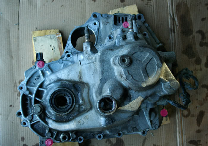
I’ve never been able to just spread the c-clip at this point and tap down on the casing to get the c-clip to seat, like some people claim. You can try this, though, to see if you find success with it. Instead, I thread four 12mm bolts (highlighted in pink) into the corners of the casing “finger tight”. Once this is done, I spread the c-clip (this time with a set of pliers I finally found instead of the two screwdrivers at the beginning of this tutorial). If the c-clip will not spread and stay open, thread the bolts down a bit further with a ratchet, but be careful that the c-clip is not being bent or damaged on the countershaft bearing.
Once the c-clip stays open, I pick the case up, flip it over, and drop it gently against a surface. EDIT per Blown90hatcH's request: To put the least stress on the transmission, and prevent any damage to the aluminum casing or internals, it is advised to drop the casing on to something that can absorb any impact - i.e. thick phone book, block of wood, etc. Also, sometimes it is possible to simply do this process in the air, without dropping the transmission. The weight of the countershaft will then cause the countershaft to slip down into the c-clip and lock it into the bearing’s guide for the c-clip. Like the noticeable “clunk” when you first opened the c-clip and dropped the countershaft, you will hear another noticeable “clunk” when the countershaft falls into place.
NOTE: If you didn’t clean out the oil in the casing, you may want to consider flipping the case over so that the bottom side of the transmission (the side which faces the ground when installed in the car) never faces downward. This will prevent any oil from seeping out through the gap between the two case halves where the gasket sealer is required to absolutely get a proper seal. Remember, gravity pulls down, so you want the best seal possible at the bottom and sides of the transmission, where the oil spends the majority of its life, sitting overnight and what not. This is easier if you just clean the oil out, though.
Flip the transmission back over and observe the c-clip. Make sure it is in properly.
Reinstall all of the 12mm bolts that hold the transmission halves together and torque them down to 20 lb.-ft. in a crisscross manner, starting from the middle and working your way out and around. Be sure to pay attention to any brackets that need to be installed with these bolts. These bolts will strip fairly easily if over-tightened. As a general rule, “hand tight” with a 3/8” ratchet will suffice and normally prevent any stripping. Reinstall all remaining pieces in whatever order you choose. It is a good idea to put sealer on the c-clip bolt’s threads. You can stay clean by using a �” extension to install it and thread it in. It will torque down to 18 lb.-ft. Again, “hand tight” will work fine if no torque wrench is available. Over-tightening this can result in cracking the transmission casing itself. So be careful. The 14mm reverse idler shaft bolt is actually pretty tight. 33 lb.-ft. is recommended, “hand tight” on the tighter side works fine. Again, torque wrenches are always good insurance.
You can thread the two 12mm bolts in to the casing which contain the shift fork springs and ***** now, as well. I have found though, that putting them in with the transmission vertical can sometimes lead to problems with shift fork movement (I have jammed two shift forks this way in such a fashion that it would not move out of neutral when pushing the shifter). Instead, I have found it easier to install these with the transmission’s bottom facing upward. Prop it up with a board, and then drop the ***** into the holes. Thread in the two bolts with the springs and lightly tighten them (these strip INCREDIBLY easily). I think 12 lb.-ft. is required. Try whichever way you wish, but this way has worked flawlessly every time for me.
Go ahead and flip the transmission back over, test the motion of the mainshaft by spinning it several times both ways. Use that Phillips screwdriver to row through the gears, making sure the mainshaft still spins in each gear.
Congrats, you’re finished!
Also, scrape off the old gasket sealer on the mating surfaces of both transmission case halves. Razor blades or gasket scrapers work well. Just be careful not to gouge the mating surface much with the blades. Then wipe it off with the carb cleaner and paper towel to keep it clean and dry. Another thing to look out for which may hinder the sealing of the case halves are scores that may need filed down. Mine did have some damage, highlighted in orange, which I filed down and wiped down.
With that done, we can get back to reassembly. Put the differential back in. Next, align the gear clusters with the shift forks like so, and reinstall them in the bell housing.
NOTE: This is a billion times easier with two people, as it can be quite difficult to both hold the gear clusters and turn the differential if the countershaft’s final drive pinion gear is having trouble lining up with the final drive ring gear of the differential.
Once complete, install the shift change assembly and the reverse idler gear. Make sure that the shift rod in the casing is in neutral, as well as all three shift forks. In neutral, the shift assembly will drop down into its place in the casing. Just maintain upward pressure of the shift forks with right index finger and downward pressure on the shift change assembly’s alignment rod with your left thumb, as seen in the right photo. Once in, reinstall the three 10mm bolts. Only tighten them gently by hand, as they can be easy to strip out. In the left photo, you can see the pin on the reverse idler that needs lined up with the slot in the transmission casing.
Next, place the reverse change holder in its place, aligned with the 5/R shift fork and the reverse idler gear. Thread its two 10mm bolts in gently by hand. Finally, make sure to move the alignment tab of the mainshaft washer to roughly the 12 o’clock position – you can see where this tab locates in the upper casing.
NOTE: Before spreading the gasket sealer on the mating surface of the bell housing, it may be helpful to run through closing the transmission case once or twice if it is your first time. This may help eliminate any surprises and resulting frustrations. As much as I have done this, I still hit snags every so often. I had a differential bearing with a slight burr prevent the casing from falling down completely. I spent about thirty minutes looking for the problem before finding it, and by that time the gasket sealer was spent.
Comfortable with the next few steps, go ahead and spread the gasket sealer. I strongly recommend Honda Bond, as that stuff is probably used to seal cracks in the Hoover Dam, but I’ve used almost all variations of RTV Sealant (gray, blue, red, black) with great results. Yes, I was being cheap.
Once you have gasket sealer spread all around the mating surface of the bell housing, go ahead and slide the upper casing down over the gear cluster, making sure you don’t bump the tab you aligned at 12 o’clock. The picture on the right shows the “thumbnail” gap that you’ll normally see when the case bottoms out on the shift change assembly’s alignment rod.
The easiest way I’ve found to drop the case further down is to use a Phillips screwdriver and use it to select various gears in the transmission. I’ll normally go for 2nd to 1st, and then 4th to 3rd. At the same time you perform this, it may be beneficial to press down gently on the top of the case, although not required. The casing will drop down almost immediately as long as nothing is preventing it.
I’ve never been able to just spread the c-clip at this point and tap down on the casing to get the c-clip to seat, like some people claim. You can try this, though, to see if you find success with it. Instead, I thread four 12mm bolts (highlighted in pink) into the corners of the casing “finger tight”. Once this is done, I spread the c-clip (this time with a set of pliers I finally found instead of the two screwdrivers at the beginning of this tutorial). If the c-clip will not spread and stay open, thread the bolts down a bit further with a ratchet, but be careful that the c-clip is not being bent or damaged on the countershaft bearing.
Once the c-clip stays open, I pick the case up, flip it over, and drop it gently against a surface. EDIT per Blown90hatcH's request: To put the least stress on the transmission, and prevent any damage to the aluminum casing or internals, it is advised to drop the casing on to something that can absorb any impact - i.e. thick phone book, block of wood, etc. Also, sometimes it is possible to simply do this process in the air, without dropping the transmission. The weight of the countershaft will then cause the countershaft to slip down into the c-clip and lock it into the bearing’s guide for the c-clip. Like the noticeable “clunk” when you first opened the c-clip and dropped the countershaft, you will hear another noticeable “clunk” when the countershaft falls into place.
NOTE: If you didn’t clean out the oil in the casing, you may want to consider flipping the case over so that the bottom side of the transmission (the side which faces the ground when installed in the car) never faces downward. This will prevent any oil from seeping out through the gap between the two case halves where the gasket sealer is required to absolutely get a proper seal. Remember, gravity pulls down, so you want the best seal possible at the bottom and sides of the transmission, where the oil spends the majority of its life, sitting overnight and what not. This is easier if you just clean the oil out, though.
Flip the transmission back over and observe the c-clip. Make sure it is in properly.
Reinstall all of the 12mm bolts that hold the transmission halves together and torque them down to 20 lb.-ft. in a crisscross manner, starting from the middle and working your way out and around. Be sure to pay attention to any brackets that need to be installed with these bolts. These bolts will strip fairly easily if over-tightened. As a general rule, “hand tight” with a 3/8” ratchet will suffice and normally prevent any stripping. Reinstall all remaining pieces in whatever order you choose. It is a good idea to put sealer on the c-clip bolt’s threads. You can stay clean by using a �” extension to install it and thread it in. It will torque down to 18 lb.-ft. Again, “hand tight” will work fine if no torque wrench is available. Over-tightening this can result in cracking the transmission casing itself. So be careful. The 14mm reverse idler shaft bolt is actually pretty tight. 33 lb.-ft. is recommended, “hand tight” on the tighter side works fine. Again, torque wrenches are always good insurance.
You can thread the two 12mm bolts in to the casing which contain the shift fork springs and ***** now, as well. I have found though, that putting them in with the transmission vertical can sometimes lead to problems with shift fork movement (I have jammed two shift forks this way in such a fashion that it would not move out of neutral when pushing the shifter). Instead, I have found it easier to install these with the transmission’s bottom facing upward. Prop it up with a board, and then drop the ***** into the holes. Thread in the two bolts with the springs and lightly tighten them (these strip INCREDIBLY easily). I think 12 lb.-ft. is required. Try whichever way you wish, but this way has worked flawlessly every time for me.
Go ahead and flip the transmission back over, test the motion of the mainshaft by spinning it several times both ways. Use that Phillips screwdriver to row through the gears, making sure the mainshaft still spins in each gear.
Congrats, you’re finished!
Last edited by Honda Bull; 12-07-2008 at 04:58 PM.
The following 2 users liked this post by Honda Bull:
The following users liked this post:
Trending Topics
12-03-2008, 09:17 PM
#13
Honda-Tech Member
Good write up man. I never put mine together although I have about 200 images of tranny tear downs and rebuilds in hopes to one day find time to do it. Please recommend the use of an thick phone book to drop the tranny gently onto. I see so many people drop the trans onto the ground to get the shaft to drop into place.
Also, thank you for telling people about the thrust and shim washers.
Also, thank you for telling people about the thrust and shim washers.
12-03-2008, 09:51 PM
#14
Junior Member
Join Date: Oct 2008
Location: center valley, Pa, lehigh
Posts: 26
Likes: 0
Received 0 Likes
on
0 Posts
Thank you sir! I bought my car with a broken GSR trans, I have been meaning to rebuild it and it's not near as impossible as I thought. Hats off to you.
 12-04-2008, 09:43 PM
#17
Honda-Tech Member
Thread Starter
Join Date: Nov 2004
Location: 40.201N, 77.189W, PA
Posts: 4,738
Likes: 0
Received 7 Likes
on
4 Posts
^^^ Indeed. And now that I think about it, I skipped out on explaining the gear teeth. I've seen worse than that gear work perfectly fine; that, and I simply can't afford another gear right now are why I didn't even bother. I was a bit more worried about the synchro teeth on the sleeve to be honest. They were on the poor side for sure.
LOL. That or against a board is all I've ever done. :p But yes, a phone book would work excellent and remove all of the shock. I'll edit that. 
12-05-2008, 08:39 AM
#18
Solbros Owns Me
I used to drop trans upside down, but not anymore.
Best thing I found is a nice long(and beefy) flat head. Stick it in the circlip groove and pry the countershaft up onto the circlip. Snaps into place with no muscling of the case.
Best thing I found is a nice long(and beefy) flat head. Stick it in the circlip groove and pry the countershaft up onto the circlip. Snaps into place with no muscling of the case.
12-05-2008, 08:55 AM
#19
Solbros Owns Me
Here's some more pics to add to this thread(will be a great resource for lots of people)...
Customer complaining of 3rd gear scratch at high revs....B16 S1 trans.
Here's the 3-4 sleeve, showing 3rd gear side
As you can see, not in good shape.
Here's the synchro teeth for 3rd gear. True, we would probably be OK with just a sleeve set, but I want to do the gear as well, to make 3rd MINT as new.
As you can see, the teeth are pretty mauled. Synchro to gear clearance was good, so that's a plus though!
Pics from celly....horrible quality
12-05-2008, 11:24 AM
#21
Solbros Owns Me
Whatever floats your boat
I have an MR-2 turbo trans here that the 5th gear slider is completely stripped
Toyota was weird with it, and only had every other tooth run completely over the synchro/gear...1/2 the strength
I have an MR-2 turbo trans here that the 5th gear slider is completely stripped
Toyota was weird with it, and only had every other tooth run completely over the synchro/gear...1/2 the strength
12-05-2008, 12:37 PM
#24
Honda-Tech Member
And pry too hard and watch the case split where the large plug goes into.


